


Resource
From WiFi to LoRaWAN: A Step-by-Step Guide to Superior IoT Connectivity - Part 2
Published on 02 Jul, 2024 by Neil
In the previous blog post, we described the steps taken to extend the connectivity of an existing product to include LoRaWAN. The choice of hardware and the LoRaWAN MAC library choice was also covered. In this post we will look at hardware integration, the initial bring-up and debugging of the LoRaWAN module and the problems encountered.
Hardware Integration
The first stage of the hardware integration process is to create a schematic of the circuit. Even if there is no requirement to manufacture a PCB, separating the design process from the wiring is essential to reduce mistakes. Below is a simple schematic only showing power supply and digital IO connections:

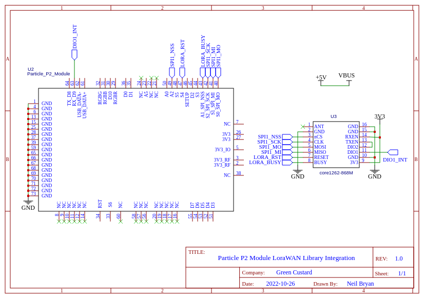
The P2 module can be ordered with an evaluation board (P2 EVAL BOARD). The headers are marked with the same designations as the pads on the P2 module. This allows for DuPont jumper cables to be used to connect the P2 to the Core1262-HF via 0.1” breadboard.
Development Setup

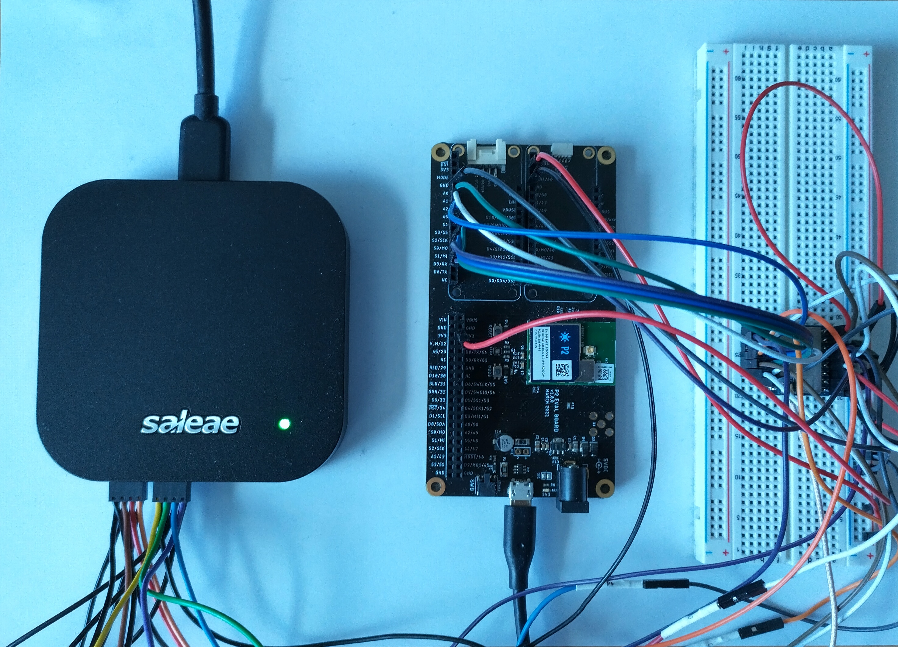
Saleae Pro 16 logic analyser, P2 eval board and the Core1262-HF LoRa module.
Hardware Bring-up
The Core1262-HF runs from a 3V3dc supply which is derived from the P2 eval board. The power requirement during transmission at 14dBm is 45mA. This is well within the limits of the 3V3 switcher on the P2 eval board.
Once the DC supply rails (including ground) have been added, the SPI interconnects can be populated and at the same time monitoring lines for the logic analyser are fitted as per the schematic. The Particle Workbench can be used with a cloud-based compiler or a local toolchain. All the development was performed using a local toolchain.
DIO1 Interrupt Source
The SX1262 can generate an interrupt from eleven different sources. Not all are required to drive the MAC layer and some can be enabled for debugging. The table below describes the various sources:

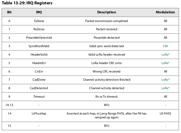
The presence of certain interrupts need to be reported to the P2 module so that the interrupt can be serviced and corresponding actions taken. This is achieved by connecting the DIO1 pin from the Core1262-HF to to pin D9 on the P2 eval board. The code running on the P2 is configured as below, for both the interrupt source and the SPI pins. The pin numbers (A5, D9, A1, …) correspond the the pad numbers on the P2 module.
/* Microcontroller - SX126x pin configuration.          */
int PIN_LORA_RESET = A5;    /* LORA RESET               */
int PIN_LORA_DIO_1 = D9;    /* LORA DIO_1               */
int PIN_LORA_BUSY  = A1;    /* LORA SPI BUSY            */
int PIN_LORA_NSS   = A2;    /* LORA SPI CS maybe D13?   */
int PIN_LORA_SCLK  = S2;    /* LORA SPI CLK             */
int PIN_LORA_MISO  = S1;    /* LORA SPI MISO            */
int PIN_LORA_MOSI  = S0;    /* LORA SPI MOSI            */
int RADIO_TXEN     = -1;    /* LORA ANTENNA TX ENABLE N/A   */
int RADIO_RXEN     = -1;    /* LORA ANTENNA RX ENABLE N/A   */
One other input is required to the P2 - LORA_BUSY, an active high value to denote that the LoRa module cannot receive further SPI commands until the currently executing command has completed. An output from the P2 (LORA_RESET) is used at system start-up to initialise the core logic within the SX1262.
During the LoRaWAN MAC initialisation stage, parameters to describe the MAC configuration are passed through to the MAC-layer.
/* From the Beegee Tokyo repo: */
static lmh_param_t lora_param_init =
{
    LORAWAN_ADR_OFF,
    LORAWAN_DEFAULT_DATARATE,
    LORAWAN_PUBLIC_NETWORK,
    JOINREQ_NBTRIALS,
    LORAWAN_DEFAULT_TX_POWER,
    LORAWAN_DUTYCYCLE_OFF
};
These correspond to:
- LORAWAN_ADR_OFF - Disable the adaptive data rate;
- LORAWAN_DEFAULT_DATARATE - Set the default data rate, in this case it is DR_3 which is spreading factor 9 (SF9);
- LORAWAN_PUBLIC_NETWORK - Allow connection to a public gateway;
- JOINREQ_NBTRIALS - This determines the number of retries to connect to the LoRaWAN network, 5 is a typical value;
- LORAWAN_DEFAULT_TX_POWER - The transmit power, we use TX_POWER_0 for use in the office (0dBm) to avoid overloading the RF front end of the gateway which is located nearby.
- LORAWAN_DUTYCYCLE_OFF - This is disabled for testing.
Here we use the pin definitions to configure the underlying data structure (hwConfig). This is passed to the LoRa library to allow for initialisation of the hardware interfaces etc.
   // Define the HW configuration between MCU and SX126x
    hwConfig.CHIP_TYPE           = SX1262_CHIP;       // Example uses an eByte E22 module with an SX1262
    hwConfig.PIN_LORA_RESET      = PIN_LORA_RESET;    // LORA RESET
    hwConfig.PIN_LORA_NSS        = PIN_LORA_NSS;      // LORA SPI CS
    hwConfig.PIN_LORA_SCLK       = PIN_LORA_SCLK;     // LORA SPI CLK
    hwConfig.PIN_LORA_MISO       = PIN_LORA_MISO;     // LORA SPI MISO
    hwConfig.PIN_LORA_DIO_1      = PIN_LORA_DIO_1;    // LORA DIO_1
    hwConfig.PIN_LORA_BUSY       = PIN_LORA_BUSY;     // LORA SPI BUSY
    hwConfig.PIN_LORA_MOSI       = PIN_LORA_MOSI;     // LORA SPI MOSI
    hwConfig.RADIO_TXEN          = RADIO_TXEN;        // LORA ANTENNA TX ENABLE
    hwConfig.RADIO_RXEN          = RADIO_RXEN;        // LORA ANTENNA RX ENABLE
    hwConfig.USE_DIO2_ANT_SWITCH = true;              // Example uses an CircuitRocks Alora RFM1262 which uses DIO2 pins as antenna control
    hwConfig.USE_DIO3_TCXO       = true;              // Example uses an CircuitRocks Alora RFM1262 which uses DIO3 to control oscillator voltage
    hwConfig.USE_DIO3_ANT_SWITCH = false;             // Only Insight ISP4520 module uses DIO3 as antenna control
    hwConfig.USE_RXEN_ANT_PWR    = false;             // eByte E22 module only.
    hwConfig.USE_LDO             = false;
From sx1262-board.cpp, the code that calls the Arduino GPIO library to configure the SPI hardware, bus speed, operating mode and interrupt line:
// No need to initialize DIO3 as output everytime, do it once and remember it
bool dio3IsOutput = false;
void SX126xIoInit(void)
{
    spiSettings = SPISettings(2000000, MSBFIRST, SPI_MODE0);
	initSPI();
	dio3IsOutput = false;
	pinMode(_hwConfig.PIN_LORA_NSS, OUTPUT);
	digitalWrite(_hwConfig.PIN_LORA_NSS, HIGH);
	pinMode(_hwConfig.PIN_LORA_BUSY, INPUT);
	pinMode(_hwConfig.PIN_LORA_DIO_1, INPUT);
	pinMode(_hwConfig.PIN_LORA_RESET, OUTPUT);
	digitalWrite(_hwConfig.PIN_LORA_RESET, HIGH);
	// Use RADIO_RXEN as power for the antenna switch
	if (_hwConfig.USE_RXEN_ANT_PWR)
	{
		if (_hwConfig.RADIO_TXEN != -1)
			pinMode(_hwConfig.RADIO_TXEN, INPUT);
		pinMode(_hwConfig.RADIO_RXEN, OUTPUT);
		digitalWrite(_hwConfig.RADIO_RXEN, LOW);
	}
	// If both RADIO_TXEN and RADIO_RXEN is defined they control the direction of the antenna switch
	else if ((_hwConfig.RADIO_TXEN != -1) && (_hwConfig.RADIO_RXEN != -1))
	{
		pinMode(_hwConfig.RADIO_TXEN, OUTPUT);
		pinMode(_hwConfig.RADIO_RXEN, OUTPUT);
		SX126xRXena();
	}
	SX126xReset();
}
Debugging SPI traffic
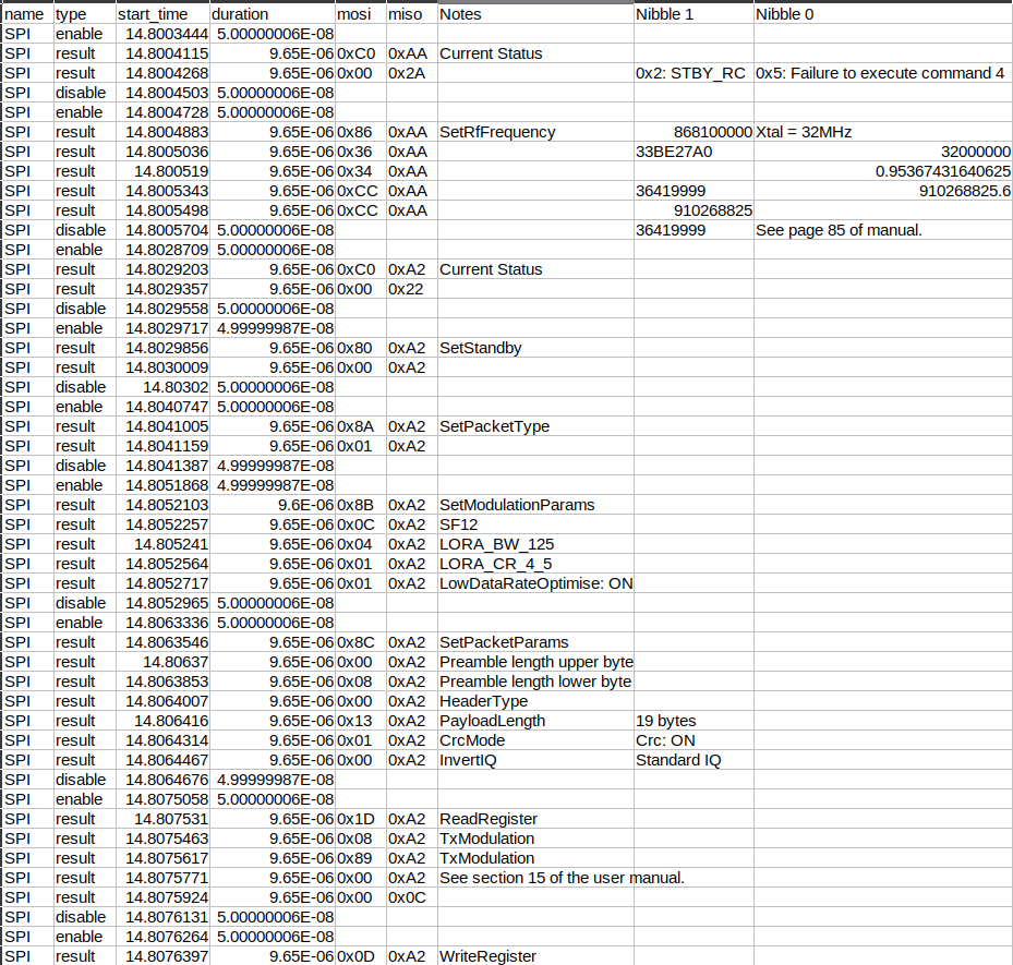
The configuration of the SX1262 and data transferred to and from the radio hardware is over SPI. It is essential that the SPI is configured correctly as there are four modes to choose from. The Core1262-HF utilises mode 0 with the data clocked MSB first.
The Saleae Logic Pro 16 was used extensively for capturing traffic on the SPI bus and decoding the data. The Saleae is a relatively low-cost tool which is extremely useful for analysing serial bus traffic. It cannot be recommended highly enough.

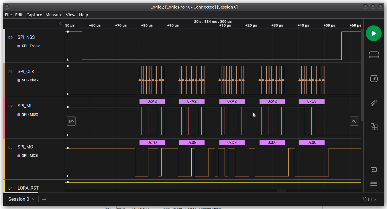
The result of a debug session with a captured, decoded log is below:

Porting the SX126x-Arduino library
The library requires several additions to allow it to run on a specific platform. The radio hardware layer is already provided and the drivers for the SX1262 work well. The library requires multiple timer functions and these need to be hooked into the operating environment, which in this cases is Particle's Device OS. The abstraction at the board-level for the library is provided by the boards directory:
$ tree boards/
boards/
├── mcu
│   ├── board.cpp
│   ├── board.h
│   ├── espressif
│   │   ├── board.cpp
│   │   ├── spi_board.cpp
│   │   ├── spi_board.h
│   │   └── timer.cpp
│   ├── nrf52832
│   │   ├── app_util.h
│   │   ├── board.cpp
│   │   ├── spi_board.cpp
│   │   ├── spi_board.h
│   │   └── timer.cpp
│   ├── p2-eval
│   │   ├── board.cpp
│   │   ├── spi_board.cpp
│   │   ├── spi_board.h
│   │   └── timer.cpp
│   ├── rp2040
│   │   ├── board.cpp
│   │   ├── spi_board.cpp
│   │   ├── spi_board.h
│   │   └── timer.cpp
│   ├── spi_board.h
│   └── timer.h
└── sx126x
    ├── sx126x-board.cpp
    └── sx126x-board.h
Here new board support files were added for p2-eval.
board.cpp - This file offers a HAL interface to the Device OS' interrupt enabling and disabling calls and a hook to obtain the board unique ID.
spi_board.cpp - A trivial call to initialise the SPI interface (using the Arduino library) is defined in this file.
spi-board.h - Provides the function declarations for the functions defined in spi-board.cpp.
timer.cpp - This is the implementation of an abstraction between ten timer instances used by the LoRaWAN MAC library and the Device OS' native timers. The timers need to have the ability to:
- run continuously with a callback on expiration
- one-shot with a callback on expiration
The LoRaWAN library makes heavy use of the timer framework to trigger asynchronous activities required by the MAC layer. Adding solid debug logging will give confidence that the timers are being added and perform as required. The level of debug should be configurable as it can become quite noisy and mask other useful log messages.
Joining a LoRaWAN network
Two methods are available to activate a device and join a LoRaWAN network:
- ABP: Activation by Personalisation - here the security keys (network session and application session) are fixed and part of the image on a specific device, or
- OTAA: Over-the-Air Activation - the device is activated by a requesting to join and then being accepted to join. This method was chosen for the P2-Core1262-HF port.
After the device EUI, application key and application EUI is added to both the device (via Commissioning.h) and to an LPWAN device on the AWS Console, the device is powered up and an attempt is made to connect. The typical flow of messages are shown in the sequence diagram below:

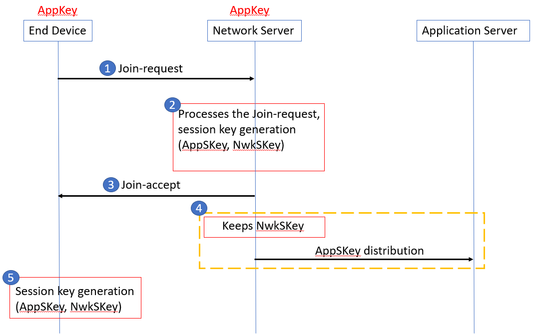
OTAA_1.0 Copyright © The Things Network.
- A join request is initiated from the P2-Core1262-HF device. This is received by the gateway and forwarded to the AWS IoT LPWAN managed service.
- The LoRa Network Server generates various session keys which are sent back in the Join Accept message.
- The Join Accept is received on the gateway and then transmitted over LoRa to the device attempting to connect.
Using the AWSLPWAN Network Analyser, the join request and accept can be clearly seen:


Unfortunately, the LoRaWAN MAC library running on the P2 never received this accept message. A significant amount of time and effort was consumed trying to understand why the join accept was never received.
During the Join-Accept debug, a backup plan was needed just in case the problem did not yield. An alternative LoRaWAN module was sourced and tested.
In the next and final post, we will look at debugging the missing Join Accept response, an alternative LoRaWAN module and communication between a device and the AWS LPWAN services.